A week ago we went for a walk round Calke Abbey grounds. Calke Abbey is National Trust and about 10 miles south of Derby.
As is usual I took a few (well a lot) of photos.
|
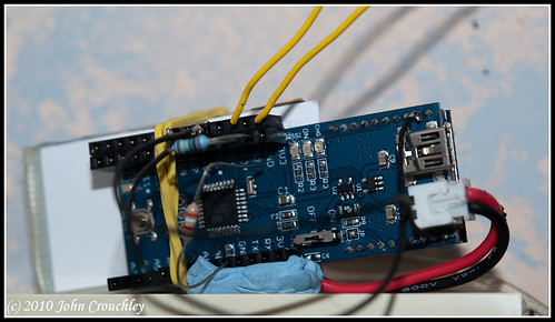
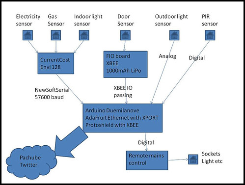
I have been extending my range of inputs to the CurrentCost, Ardunio, Xport pachube logger. A lot of devices use XML these days – and parsing the XML by hand is quite complex. I use a CurrentCost CC128 power monitor and also Twitter. Both of these have an XML interface. Over the last couple of months I have been developing a simple XML parser as an Arduino library – it is table driven and so compact and easily modified. This is now ready for release – you can download it here. The CC-128 example compiles at less than 9kB. I have included a Twitter API example and also a CurrentCost CC-128 example. The CC-128 example is being used to provide a data concentrator for CC-128. I am using an Arduino (Mini Pro 328) to take the cpu burden off the main Arduino, processing serial data at 57600 baud takes up most of the power of an Arduino. Connect the Mini Pro to the CC-128 using GND and CC-128 Tx to Mini Pro pin digital 1. The Mini Pro acts as an I2C slave for the main Arduino (simple connection – just link up GND, A4 and A5 – also 5V if you don’t have a separate power supply). I have three current cost devices feeding the CC-128 – Electricity, Gas and a light sensor. It should be quite easy to modify the example for your configuration. Master code to read from the CC128 I2C slave is roughly as follows Wire.beginTransmission(I2CADDR); Presents under the tree all ready to be opened after scrambled egg and smoked salmon brunch, with bucks fizz. Nom nom. Despite appearances the tree is vertical – just a weird branch at upper right. Updated blog to use Ingoal’s Twitter Updater The Arduino Nokia 3310 shield come from NuElectronics. I have been using this shield with an Arduino Ethernet shield together with Andrew Lindsay’s Nokia 3310 library. I upgraded the library to be compatible with multiple SPI components, you need to bend digital pin 10 so that it does not make contact and then connect it to another spare pin. This is the current state fo my home monitoring system. Just got back from Hungary – blogged here. We spent the weekend staying a the George Hotel in Castle Cary. The code I have been developing for my Current Cost meter updating to Pachube via Arduino with XPORT is ready for sharing. |


Cannot post reliably – keep getting errors
I am having great difficulty in posting anything that is not straight text – I suspect a WordPress bug (recently upgraded to 2.9) but I cannot narrow it down. It appears to be when I have links to external sites. Wonder if WordPress introduced a new security feature?
Got it – any post created with the twitter upload plugin active and WP 2.9 or greater gets garbled. Disable and delete the plugin, then create new posts – all is good.
Set up with different plugins and theme.