Etiam pulvinar consectetur dolor sed malesuada. Ut convallis
euismod dolor nec pretium. Nunc ut tristique massa.
Nam sodales mi vitae dolor ullamcorper et vulputate enim accumsan.
Morbi orci magna, tincidunt vitae molestie nec, molestie at mi. Nulla nulla lorem,
suscipit in posuere in, interdum non magna.
My HTC Desire is now two years old and the airtime plan I was on did not give me enough minutes (and was very expensive if I went over the allowance). So time for a new plan and phone.
After much looking around I decided on the HTC One X, in grey rather than white.
There are plenty of review and specs available on the web so here I am going to concentrate on what matters to me.
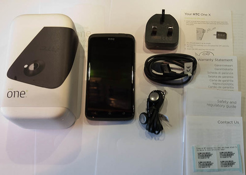
So my new phone finally arrived yesterday, the box is somewhat reminiscent of an egg box – appropriate for the time of year. In the box as well as the phone is a power supply around the same size as a normal UK plug, a USB cable, the standard ear pieces and microphone, a sim card tool and some (very little) documentation.
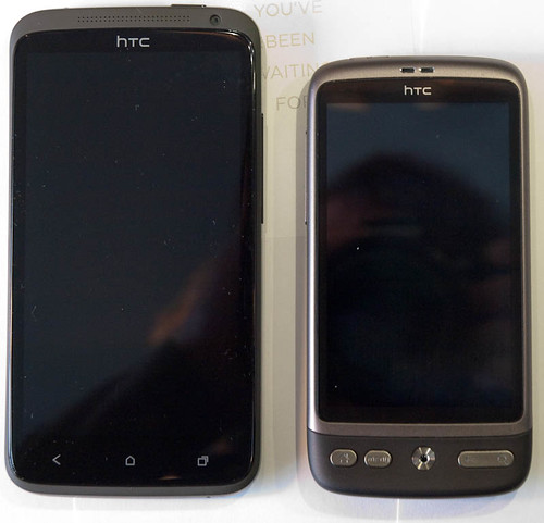
First impressions are that the phone, whilst large, is thin and quite light but solidly made and it didn’t feel at all fragile. So to compare it against the HTC desire it is thinner and lighter but the screen is significantly larger.
The back of the HTC One X is mainly blank except for the camera lens. There are some contacts along one side, presumably for docking.
So what do I like most about this phone
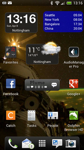
The screen is the first thing you see, and it is superb. The colours are bright and vivid and the extra size of the screen helps me (with my fat fingers) to type much more accurately. I also like the screen capture feature – here is my home screen:
The sound is clear, and the speaker is quite loud enough.
The memory (just over 2GB of phone memory available and around 25gb of storage) is more than enough for my needs. On the HTC Desire I was always running out of space. As usual this can be accessed through the USB cable from your PC.
Ice Cream Sandwich and the HTC Sense upgrades are very nice – I find using the phone easy and natural after the HTC Desire and the extra features are great.
I like the shortcut bar at the bottom, much better than just being able to access the phone feature as in the HTC Desire.
The HTC One X just feels great, natural and fast – did I forget to say it is fast.
Neutral comments
There is no removable SD card – I never took the card out of my HTC Desire and so will not miss this.
The battery is not removable – good and bad. It means you cannot carry a spare battery around for when you run out. On the plus side battery life is better than the HTC Desire and I understand that a new firmware release is about to come out (1.27) that will help increase battery life by about 40% (from several reviews I found on the web – it looks like some reviewers have been able to compare both 1.26 and 1.27). A further plus here is that as the battery is no longer a consumable it should be covered by warranty should it degrade significantly over the two years.
The HTC One X takes a micro sim card – this is just a cut down mini sim card and can easily be obtained from you provider. There are also posts on the web which describe how to cut down your mini sim to size. I purchased a micro sim cutter from Amazon which made the job easy and also gave me an adapter so that I could use the cut down micro sim card in the HTC Desire.
The volume button has moved to the other side of the phone from the HTC Desire – this will just take a little getting used to.
I wondered if the size would be a problem but it does fit nicely into my hand and is very comfortable and easy to use – even with one hand, using the screen with my thumb. If you have small hands I would try before you buy.
and the things I like least
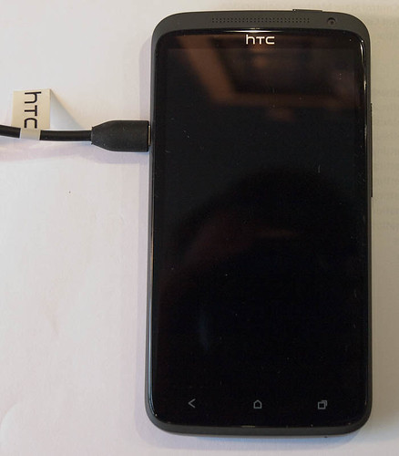
I do not like the position of the power connector, this feels wrong if you try and use the phone whilst charging, it also seems to place a strain on the connecter that would not be there if the connection was at the bottom.
I miss the little scroll device that was the centre bottom button on the HTC Desire, so convenient for navigation whilst writing text.
I used the night clock in the HTC Desire a lot, it was just right for using at my bedside. I have found an app (YANC – yet another night clock) that is similar but it is not quite as good.
So the summary, a superb phone from HTC and a phone I have fallen head over heels for. Top of the range and currently I think the best phone on the market. I am sure that I will get many happy hours of use out of this phone.
This is based upon about 10 hours of use, I will update this post in a few weeks with any new opinions.
18/Apr/2012 Update
I have been getting increasingly annoyed by some minor issues – screen glitches and HTC Sense crashing (Just get loading appear for a few seconds instead of immediately switching to the home screen). This was even more frustrating as I understood they were fixed in the latest firmware which seemed to be available elsewhere. Well today HTC released the 1.28 firmware in the UK and I am glad to say that (so far) my irritations have vanished. I guess that carrier specific firmware versions may take a little longer but it will be worth the wait. Now to see if the battery usage is any better – I have already noticed that the screen is no longer overly bright when on automatic (which it was before).
I will update again in about a week with any further issues/thoughts.
26 April 2012
Battery update. I find that most days I finish the day with about 40% battery remaining, however an hour or two playing Angry Birds can reduce that to 10%. This is mainly used for calls (1 hour a day), email, Twitter (via Plume) and browsing – your usage will vary. I charge the phone every night on my bedside table.
Still loving the phone, the only niggle I still have (not got used to yet) is the position of the charger socket. The other issues I had have gone away with time.The optical scroll device has been replaced with a teardrop shaped marker you can drag on the screen to move the cursor, and I find this to be a good replacement.
As with the HTC Desire, if you are out and about, using the phone a lot you can run out of battery, so I have a “TeckNet® iEP387 7000mAh Dual-Port 2.1Amp Output Universal USB Battery Bank” – basically a portable rechargeable – charger. I keep this in my camera bag so I always have it when out and about.
I have recently been experimenting with some XRFs from Ciseco Plc. The firmware (v0.36) on these XRFs is beta but I understand it is about to be released.
I have tested this on a Nanode and also on a Ciseco Xino for Atmel, it should work with a standard Arduino but I have not tested it.
The new features of the firmware are:
1) reduced delays when continuously sending or receiving data
2) Support for remote reset
These when taken together allow Arduinos to be remote programmed.
So to set this up we need an XRF connected to the Arduino (I’ll call this the remote XRF) and an XRF connected to your PC (the host XRF).
Wiring, the remote XRF needs GND, PWR, Rx, Tx and pin 17 hooked up – see the fritzing diagram below,
the host XRF needs to be connected serially to the host PC – e.g. by using a FTDI cable; GND, PWR Rx, Tx and pin 16 need connecting.
Remote XRF setup:
You need to give the remote XRF an ID (command ATMY) e.g. to give the ID “NN” to the node enter the AT command “ATMY NN”.
You also need to set up the baud rate to match that expected by the bootloader. This is 115200 for a UNO bootloader and 57600 for a standard ATMega386 bootloader.
For the Uno
ATBD 1C200
and for the standard Arduino
ATBD E100
Host XRF setup:
You need to tell the host XRF the ID of the remote XRF to program.
To set a remote ID of NN
ATRI NN
you also need to enable the remote reset (1 to enable and 0 to disable)
ATRP 1
Finally you need to set the baud rate as for the remote XRF.
ATBD 1C200 or ATBD E100
Now you are all set up – run the Arduino IDE, select the board type and the port for the host XRF and program.
Note: This method of programming is intolerant of any radio noise or other XRF radio traffic on the same frequency/panID. I understand future firmware updates may improve this, but at the moment you may need to try and upload more than once – the Arduino IDE will tell you if it succeeded.
Images:
Host XRF to PC.
Remote XRF to Arduino. Note Pin 17 of the XRF should be connected to the DTR line if the Arduino has a FTDI connector, also if used the capacitor value is 100nF.
I built this onto a small XRF module board that Ciseco produce. Miles assures me that these will be available soon. The boards contain a 3v3 regulator as well as sufficient prototyping space for the connections needed.
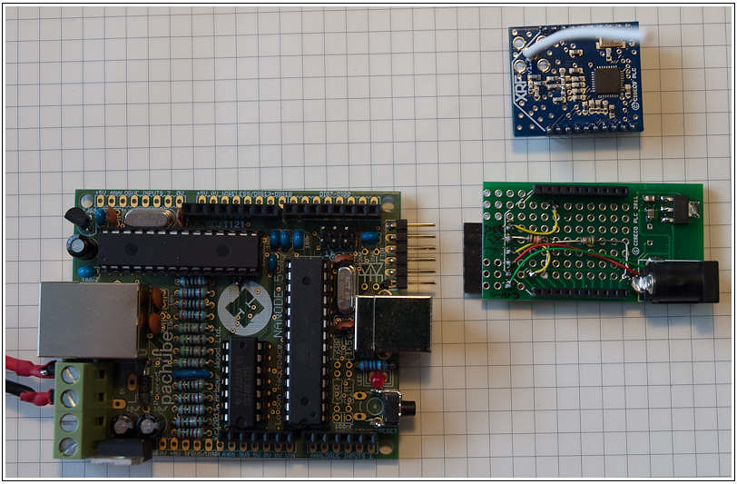
Photo of the remote setup, Nanode, XRF and XRF module board
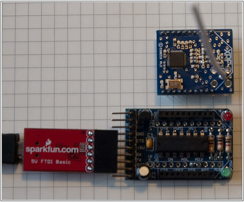
Photo of the host setup – SparkFun FTDI board, AdaFruit XBee board and XRF
Videos:
Disclosure: Miles (Ciseco) lives near to me, we met at the Nottingham Hackspace. In return for beta testing Miles supplies me with some of his kit.
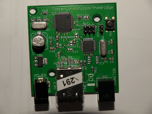
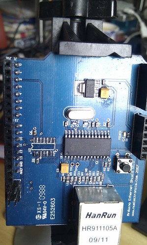
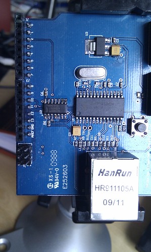
To open the CC bridge box remove three screws from the base (one under the sticker). Note at this point assume you have invalidated any warranty. Remove the board – it should look like this.
Connectors (left to right), Power – 4.5-6V @ 500mA, Ethernet mag jack, Serial port (RJ10) pins left to right Rx,Tx,GND,3v3 – note the 3v3 is supplied via a 10 ohm resistor R11 (current limiter).
Bridge across jumper 1 to disable the Wiznet W5100 ethernet chip and using your favorite technique (I used a USBTiny from Adafruit) burn the Arduino bootloader onto the AVR. Note only power the board from one source – either 3v3 from the programming device or the on board power (leave the programmers power unconnected). There are several examples on the web of using an Arduino to program a bootloader – just be aware that signals will need to be 3v3. Note the board ID needs to be “Arduino Pro or Pro Mini (3.3V, 8 MHz) w/ ATmega328”
Once the bootloader is on the board it is possible to program it using the Arduino IDE.
I used a USB to TTL FTDI serial converter (a good one is from Sparkfun). Signal levels will be 3v3 so there is no issue there, just connect up GND, board RX to FTDI TX and board TX to FTDI RX. I cut up the cable supplied for this – Farnell supply suitable RJ10 plugs (as far as I can tell these match the dimensions of the supplied plug).
Note: there is no auto reset so you need to hit the reset button once the sketch has compiled – you may need to practice this several times before you get the timing right (I did). I pressed the button when the compiled size came up on the screen, counted to three and released it – seemed about the right time.
The first sketch I loaded is the example Ethernet server sketch. You need to make one simple alteration to this. Add the following lines at the beginning of the setup routine (as well as verify that the mac and IP address are OK for your system):
pinMode(7,OUTPUT);
digitalWrite(7,HIGH);
This code will enable the W5100 ethernet chip as Digital I/O 7 is connected directly to the W5100 reset line. This line is connected via a resistor to GND and so we need to pull it up to enable the device.
Once the sketch is loaded into the board you should be able to connect a RJ45 ethernet cable and access the page from your browser.
I also notice that the board contains pads for an I2C EEPROM chip – I don’t think mine will be vacant for long, I have a 128KByte FRAM chip that will fit nicely there..
A further improvement will be to add a Micro SD card interface, I will then have all the ingredients for a cheap web server to front end my home monitoring system.
The code assumes some familiarity with the ethershield examples.
#include <etherShield.h>

static uint8_t mymac[6] = {0x54,0x55,0x58,0x10,0x00,0x28};
static uint8_t myip[4] = {192,168,1,25};
// Default gateway. The ip address of your DSL router. It can be set to the same as
// websrvip the case where there is no default GW to access the
// web server (=web server is on the same lan as this host)
static uint8_t gwip[4] = {192,168,1,1};

//============================================================================================================
// Pachube declarations
//============================================================================================================
#define PORT 80                   // HTTP

// the etherShield library does not really support sending additional info in a get request
// here we fudge it in the host field to add the API key
// Http header is
// Host: <HOSTNAME>
// X-PachubeApiKey: xxxxxxxx
// User-Agent: Arduino/1.0
// Accept: text/html
#define HOSTNAME "www.pachube.com\r\nX-PachubeApiKey: xxxxxxxxxxxxxxxxxxxxxxxxxxx"          // my API key
static uint8_t websrvip[4] = {173,203,98,29};  // www.pachube.com
#define HTTPPATH "/api/9999.csv"      // The feed

EtherShield es=EtherShield();

#define BUFFER_SIZE 500
static uint8_t buf[BUFFER_SIZE+1];

void browserresult_callback(uint8_t statuscode,uint16_t datapos){
 Serial.print("Received data, status:"); Serial.println(statuscode,DEC);
 if (datapos != 0)
 {
  Serial.println((char*)&buf[datapos]);
  // now search for the csv data - it follows the first blank line
  // I'm sure that there is an easier way to search for a blank line - but I threw this together quickly
  // and it works for me.
  uint16_t pos = datapos;
  while (buf[pos])    // loop until end of buffer (or we break out having found what we wanted)
  {
   while (buf[pos]) if (buf[pos++] == '\n') break;   // find the first line feed
   if (buf[pos] == 0) break; // run out of buffer
   if (buf[pos++] == '\r') break; // if it is followed by a carriage return then it is a blank line (\r\n\r\n)
  }
  if (buf[pos])  // we didn't run out of buffer
  {
   pos++;  //skip over the '\n' remaining
   Serial.print("CSV line is:");
   Serial.println((char*)&buf[pos]);
  }
 }
}

void setup(){
 Serial.begin(9600);
 Serial.println("Ethershield Get example");

 /*initialize enc28j60*/
 es.ES_enc28j60Init(mymac);

 //init the ethernet/ip layer:
 es.ES_init_ip_arp_udp_tcp(mymac, myip, PORT);

 // init the web client:
 es.ES_client_set_gwip(gwip);  // e.g internal IP of dsl router

 es.ES_client_set_wwwip(websrvip);  // target web server

}

void loop()
{
 static uint32_t timetosend;
 uint16_t dat_p;
 while(1){
  // handle ping and wait for a tcp packet - calling this routine powers the sending and receiving of data
  dat_p=es.ES_packetloop_icmp_tcp(buf,es.ES_enc28j60PacketReceive(BUFFER_SIZE, buf));
  if (dat_p == 0)
  {
   if (millis() - timetosend > 10000)  // every 10 seconds
   {
    timetosend = millis();
    Serial.println("Sending request");
    // note the use of PSTR - this puts the string into code space and is compulsory in this call
    // second parameter is a variable string to append to HTTPPATH, this string is NOT a PSTR
    es.ES_client_browse_url(PSTR(HTTPPATH), NULL, PSTR(HOSTNAME), &browserresult_callback);
   }
  }
 }
}
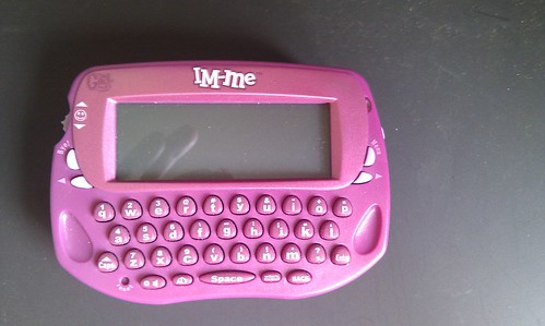
This is the first of several posts about the IM-Me pink wireless toy from Mattell. The aim of this post is to collect all of the relevant links I have found useful from the web.
You can currently get one (or more) of these toys for £8.99 at Amazon
The IM-Me is based upon the TI CC1110F32 chip, datasheet
Dave’s hacks – im-me hacking
Dave’s hacks – im-me LCD interface hacked
Travis Goodspeed’s blog on the IM-Me
Michael Ossmans blog – a $16 spectrum analyser CC-flasher – open source programmer – most useful for the SDCC open source tool chain for the CC1110
From TI:To develop software, program and debug the CC1110, the IAR Embedded Workbench for 8051 is recommended. An evaluation version of IAR EW8051 is included in the kit. This free evaluation version and a free code size limited version, can be downloaded from the web, see www.iar.com/ew8051 this is limited to 4K of code, this can be increased to 16K by following the instructions in section 9.1 of this document
Details of the CC1110 debugging interface and how to program it
The next post on this topic will look at modifying the IM-Me so that the debug interface is easily used, setting up an Arduino to program the IM-Me and the Arduino software required to interface to the IM-Me.
Further posts will then look at programming the IM-Me using the IAR EW8051 IDE www.iar.com/ew8051 (I use the 4kb code limited Kickstart edition, increased to 16kb).
Both of the major Arduino ethernet shields (standard Arduino and NueElectronics) have issues with the MISO signal which prevent them being used with other SPI devices.
The standard Arduino shield uses the Wiznet5100 chip – this chip has a flaw in that the CS signal does not tri-state the MISO line. The Wiznet application note can be found here. The relevant part is below.
Quote Basically, multiple SPI slave usage is the same as single SPI slave usage. One difference between other SPI slave devices compared to the W5100 is that the MISO output is continuously driven in the W5100 whether the /SCS is asserted as high or as low. As well, when the 5100 /SCS is asserted as high when using multiple slaves, other SPI devices cannot be read or written by the SPI master on the SPI BUS simultaneously. These problems will continue unless the recommendations listed below are followed.
Recommendations:
– When accessing another device on the SPI BUS rather than the W5100, assert the SEN pin in the W5100 as low first, then access the other devices.
– When accessing the W5100, the SEN pin should be high.
…
The W5100?s SEN signal is input from the /SCS through the inverter. If you don?t want to use the inverter, you can control each signal through the I/O port of the MCU.
end quote
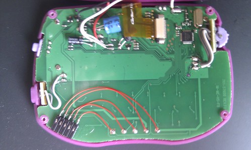
So by inverting the SS line (Arduino digital 10) and driving SEN from that fixes the issue. Here is a photo of my rather crude fix – using a CMOS 4011 quad 2 input NAND gate chip. Note this is a DFRobot clone – the pads for the PROG jumper (one connected to SEN) are reversed from the normal shield. The wire running underneath connects to the chip select line (Ardunio 10) – I went underneath for this to allow my to cut the line later if I needed another pin for chip select. Small rant – all SPI shields seem to assume they can use CS on pin10 – why cannot this come out to a solder jumper or pads so that I can select any pin as chip select. Using multiple SPI devices is a real pain because of this.
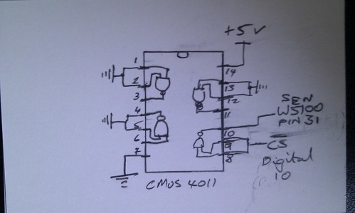
By request the circuit diagram for this is also shown. Note that in the board pics I placed the 4011 upside down (I could then glue it to the board). Also all unused inputs of the 4011 (I only use one gate out of 4) are grounded (because this is good practice with CMOS devices), even here I made one of my many mistakes – the diagram is wrong in fact pins 5&6 are grounded not 4&5.
Any inverter would have done, I just happened to have a 4011 in my ‘bits’ box.
———————————————————————————
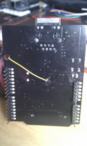
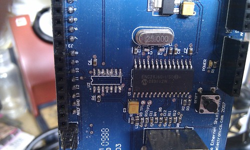
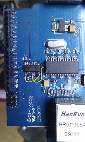
The NueElectronics shield uses a 74HCT08 chip to boost the MISO and INT signals to 5V levels, this chip is not tri-state and so the MISO line is always driven.
Replacing the 74HCT08D with a 74AHC125D is an almost direct replacement – cut the 74HCT08D off and tidy up the pads,
the connection between pins 1&2 and pins 4&5 needs to be broken and then the 74AHC125D soldered in the same place. Then add two small jumper wires: pin1 connected to GND (for the INT line), p4 connected to SS (Arduino digital 10) for the MISO line (Arduino digital 12).
A while back @andrewoke was bemoaning the availability of an open source HD4470 I2C LCD and keypad controller. So I wrote one – the code fits into an Attiny2313 (just). ATTiny2313 chips are available for under $2.
The AVRDude command line I use to program the ATTiny2313 with Adafruit’s USBTiny programmer is: (note the fuse change – this is to run the 2313 at 8MHz) avrdude -p attiny2313 -c USBTiny -u -U lfuse:w:0xE4:m -U flash:w:I2C_LCD.hex -U eeprom:w:I2C_LCD.eep
*********
Notice – the protocol to be used has pretty much completely changed. I am adopting the aProtocol described on the OpenKontrol web site
aProtocol is essentially a hub polling devices, it does allow for devices to announce events but in the main it is polling.
The aProtocol is still work in development, I have joined the team to help make it into a robust home monitoring and automation protocol.
*********
Now that I have decided on the hardware (JeeNode V4 for nodes and Arduino for data logger) I have started to look at the data format and protocols between the nodes/sensors and the data logger. It is clear that there are three basic types of data to be dealt with
a) Current reading (sensor to data logger ). This includes events (e.g. PIR trigger or Battery Low).
b) Totals & counts (sensor to data logger). Note: totals/counts are never cleared down (unless the node is reset), the receiver of the data needs to keep track of the last total and subtract it. This makes it easy to get total for last 15 minutes, total for day etc.
c) Requests and instructions (data logger to sensor)
Low level protocol will ensure message integrity (CRC check or similar). If the sending message requests it then the receiver will ack the message (most messages will not use this – see message descriptions).
Some means to assess transmission quality (number of missing packets) is needed. The low level transmission protocol will send an incrementing sequence number (byte) with every message. Each node will also track the last sequence number received from the data logger. The data logger will keep a table; for every node the last sequence number sent and received will be stored.
The basic mode of operation is that nodes will send out data at predetermined time intervals (say every x seconds – but may differ for some sensor types), if a message goes astray or is corrupted then this is not important and we will get the value next time. Whilst this is not completely accurate (for example for energy readings) in that some values may be lost it is good enough for monitoring purposes. We require to know if some messages have arrived successfully so these will request an ack, (and re-transmission if no ack is received) in these cases the receiver should be able to accept the same message more than once without issues as the ack may be lost.
All sensor to data logger messages will be broadcast (destination node 0) – this facilitates having more than one listener – although only the data logger will ack (if ack is requested).
All messages will be in the following format : 12 bytes, human readable ascii to facilitate debugging (32 bit values will be sent as hex). Numeric information will be zero padded to the left (e.g. 123 will be sent as 00000123).
Message Format
Byte #
Name
Meaning
0
msg_Type
Message type – list below
1
msg_NodeID
Sending node ID (A-Z)
2
msg_SnsID
Sensor ID within node (A-Z) + special types
3
msg_SnsType
Sensor type – list below
4
msg_Data1
Data to be sent
5
msg_Data2
6
msg_Data3
7
msg_Data4
8
msg_Data5
9
msg_Data6
10
msg_Data7
11
msg_Data8
Message Types
Type
Meaning
A
B
C
D
E
Echo – Request a I’m here message
F
I’m here
G
H
I
J
K
L
M
N
O
P
Q
R
Sensor reading
S
Request reading
T
Request total
U
V
X
Node (re)started
Y
Z
Some sensor IDs are reserved for special use. These are: (lowercase letters)
ID
Meaning
a
Total of missing received sequence numbers (16 bit)
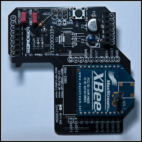
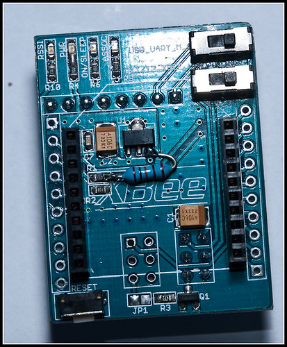
The Arduino XBee shield uses a resistor divider to connect the TTL 5V Arduino Tx to the XBee Din line. This has the side effect of pulling the Din line to GND if the Arduino is not asserting the Tx line. Problem is that the Arduino does not have control of the TX line during the brief power up sequence.
Series one (802.15.4) Xbees use a low on DIn during power up to force entry into command mode at 9600 baud – an escape for when all else fails.
This means that you cannot use the XBee for about 10 seconds after power up. To avoid this you need to pull up the Arduino Tx line by attaching a 10K resistor between Tx and 5V. Here are a couple of shields I modified
Updated 26/2/2010
I have been looking at revisiting my home monitoring setup for some time. Whilst I have considered plug computers and other slugs as the hub for this I keep coming back to the Arduino. An Arduino has enough CPU power, is cheap, very low power and I can maintain it should it develop a fault.
For the sensor communications I have decided to standardize on the JeeLabs JN4. Most sensors will connect directly to the sensor controllers, but for the CC128 then I will use a bare board Arduino as a data concentrator.
For the first part of this project I will build the data storage unit. This will have:
1) Seeeduino 328 – chosen due to the additional 3.3v power available.
Update 24/2/10: I am revising this decision as the Seeeduino has placed the 500mA fuse on the 5v line (not on the USB 5v line), I need more than this (it is the LCD back light that draws most of this) and the fuse keeps cutting power. I will probably end up with a standard Duemilanove and put a 3.3v regulator in for the 3.3v devices.
Update 25/2/10: Measured current required – 305mA (180mA without the LCD) – so it must be the regulator cutting out because the heat sink is not adequate. Moved to Duemilanove, with 100mA 3.3v LDO regulator and although the 5v regulator does get hot I do not have any cutout problems.
3) XBee-pro 802.15.4 for serial wireless communications connecting to the Arduino via a XBee shield.
Update: Using the JeeLabs JN4 with RFM12B operating at 868MHz for the wireless communications
4) 128Kbyte I2C FRAM (RAMTRON) this will be used to hold message queues – this is 3.3v
5) 2GB SD card – initially with uALFAT controller (I2C 3.3v), but I intend to use a SD card directly for the final version.