Categories

A sample text widget

Etiam pulvinar consectetur dolor sed malesuada. Ut convallis euismod dolor nec pretium. Nunc ut tristique massa.

Nam sodales mi vitae dolor ullamcorper et vulputate enim accumsan. Morbi orci magna, tincidunt vitae molestie nec, molestie at mi. Nulla nulla lorem, suscipit in posuere in, interdum non magna.

XBee wireless programming of Arduino

Succeeded today in remote wireless programming a Funnel IO Arduino clone.

I had previously followed the instructions from LadyAda and got a very flaky program load – particularly with large files. Now following the Funnel IO route I have a reliable and solid way of remotely programming the board. I am using the Arduino IDE to upload the code. This also works well with direct use of avrdude.
The secret lies in the XBee configuration – this works for me.

Command Coordinator (i.e. a PC side) End device (i.e. a FIO side)
ATRE – Reset to defaults
ATBD 4 4
ATID 1234 1234
ATMY 0 1
ATDL FFFF 0
ATD3 3 5
ATIC 8
ATIU 0
ATIA FFFF
ATRR 3
ATRO 10 10
ATWR – Write the changes
ATCN – Exit command mode

I think the main difference from my first attempts lies in the destination address (ATDL). I will test further to see what is needed – also how well this works for other Arduino types.
Gas meter to CurrentCost to Arduino to Pachube up and running

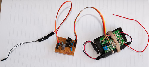
Built to circuit and connected it all up. Bluetacked reed switch to meter and board + cc dev board + 2 AA batteries into small container.
CurrentCost dev board with gas meter circuit
P7122949
P7122950
CurrentCost meter connect to Pachube via Arduino. In order to try and get some idea of energy usage and comparison with the electricity usage I am logging KW. The calculations are:
Gas KWhours = cubicmeters * correctionfactor * calorificvalue / 3.6
1 pulse is 0.01 cubic meters
correctionfactor is 1.022646 (from gas bill)
calorificvalue is 39.4 (from gas bill)
So 1 pulse is 0.1119223 KWh.
Average KW = totalKWh * 3600 / measurementperiod(seconds)
I have set the measurement period to 5 minutes – this gives a reasonable resolution. At peak use I seem to get about 1 pulse every 18 seconds. Latest – I now update every 15 minutes – that way Pachube displays every update.

Last 24 hours Gas KWatts

Why the diode in the circuit?

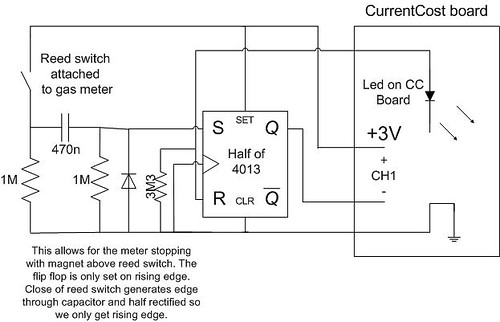
When the switch opens the falling edge will cause a negative pulse on the 4013 input. The diode removes that negative pulse.

Input to 4013 without diode – one pulse (on/off) – zero volts is the centre line. The signal goes negative to minus 1.44 volts. Positive pulse comes from direct connection to +3 volts, negative pulse is smaller because capacitor has to discharge through 1M resistor.
P7112944

Input to 4013 with the diode – the negative signal is almost totally removed. The signal goes negative to minus 0.35 volts.
P7112945

Final gas meter to current cost circuit

Here is the final circuit I will use, the resistor and capacitor values give a time constant of about 0.5 sec – I’m sure many other values would work but I have these ones in my box.
I have added a pull down resistor on the reset line just to make sure it is low unless deliberately raised high. I will build this over the weekend.
ccgas

Energy tracking part 2a

This is the CurrentCost development board. Note the 10 pin programming header – the leftmost pins are at 0V the rightmost at the positive supply voltage. I have attached a wire to the anode of the led.
Currentcost dev board Currentcost dev board

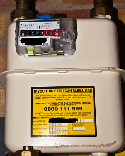
This is my gas meter – there is a cut out at the bottom right of the display that can accept a reed switch.
gas meter detail
Gas meter

Energy tracking part 2

@MartinDix from CurrentCost kindly sent me a dev board so I could interface other feeds to the CurrentCost meter. After some experimentation this is the circuit I intend to use. I have not yet fully finalised values of components but it seems to work pretty well on the breadboard. Note my dev board is version 1.1, the positive connection to ch1 is connected to positive power line.
The idea of the circuit is that a rising edge (start of pulse) is latched until it has been transmitted to the meter.
ccgas

Another photo published!

http://www.classic-sailing.co.uk/start-port/swansea

Energy tracking

Purchased a Current Cost CC128 meter and it arrived yesterday. No problem getting it going and it is now connected to an Arduino with a XPORT Ethernet shield. I got NewSoftSerial reading from the CC128 at 57600 baud and controlling the XPORT at 19200 baud. I am logging the temperature and watts usage to Pachube every 30 seconds.
Last 24 hours temperature
Last 24 hours electricity useage

Schmap and Barry Island

I got a photo published! Schmap have included one of my Barry Island pictures on their interactive guide.
Barry Island

Capacitance meter (1)

Whilst I was looking at the ATmega168 datasheet to see if I could improve the NewSoftSerial library speed I came across the analog comparator – this takes a reference voltage at digital input 7 and a voltage to be compared at digital input 6. Any time the voltages are equal (rising or falling – you choose) you can get an interrupt. Even better it will trigger a snapshot of Timer 1 (a 16 bit timer/counter), the spec calls this a Capture.
I started thinking about a capacitance meter using this.
Capacitors charge up with a time constant of T=RC, by measuring the time to charge to 63.2% of the supply voltage and knowing R we can caluate C. This has been used before to produce an Arduino Capacitance Meter. The span and accuracy of such meters has been limited by how accurately they can measure the time. Using the Analog Comparator and Timer 1 should enable me to get a much more accurate measure. Using a prescalar the input to Timer1 can be 16Mhz, 2Mhz, 250Khz, 62.5KHz or 15625Hz – on a 16bit counter this gives a large number of possible ranges.
I decided to go with 4 ranges (based upon a minimum count of 30 and a maximum count of 60000 – to get enough resolution and not get too close to overflow).
R=2M2 Timer1=16Mhz Range 0.8pF – 1.7nF
R=2M2 Timer1=62.5Khz Range 218pF – 436nF
R=1K Timer1=250MHz Range 120nF – 240uF
R=1K Timer1=15625Hz Rage 1.9uF – 3840uF
The meter will be auto ranging – I will use the Timer 1 Capture interrupt and the Timer 1 Overflow interrupt. I have built a proof of concept and it all seems OK so I will be building the meter over the next few weeks (as I get time).